Q: Can I wire a Max Flow Meter with an analog transmitter to loop power (2-wire) or a non-isolated (3-wire) system?
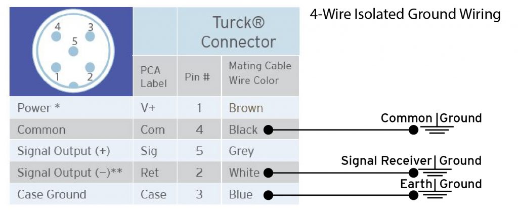
Max: We have many customers using Max Precision Flow Meters with the 4-20 mA Analog transmitter option that ask about alternative wiring methods to the standard 4-wire fully isolated installation shown in the manual. To download the manual for you meter, go to www.maxmachinery.com/downloads and select the manual for your meter from the list. Here is the wiring diagram from the manual:

Max Precision Flow Meters are designed to be in a fully isolated electrical system for optimum performance and maximum data transfer with the least electrical interference that is possible.
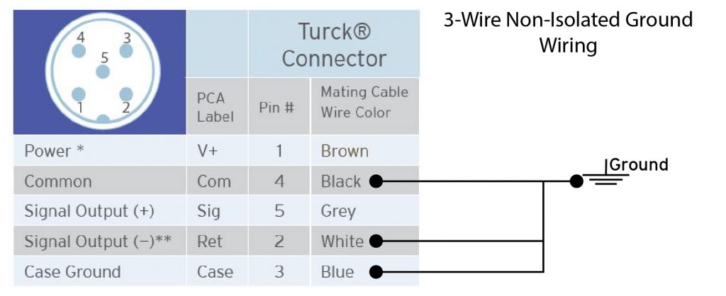
If your system is not designed to take advantage of the maximum performance of your Max Flow Meter and the cost to upgrade is prohibitive, Max Meters can be used in a non-isolated (3-wire) system. Max Flow Meters will not operate in a 2-wire or loop powered system as the power requirements for the meter exceed loop power specifications. For non-isolated systems where a single ground is provided, follow the diagram below to wire in any Max Flow Meter with an analog transmitter:

Once you have confirmed your system is providing measurement data, be sure to verify and filter out the noise that will occur due to the shared ground. Depending upon the data stream, the application environment, and the other equipment in use, the interference may be none, little, or significant.
If you are still having trouble with the data you are collecting, you may always reach out to Max Machinery or one of our sales partners for free technical support. Click Here to Contact Us.
TECH-ART-1021 -Grounding Analog Transmitters – Download the PDF HERE.